


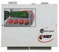
Battery operated 16 input-channel datalogger with Ethernet interface
Multilogger
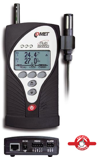
- use DATALINK: display current values or download values from
device memory to your PC - view current measured values using your web browser
- third-party applications to read the actual measured values using
universal protocols SNMPv1 and XML - send data to COMET DATABASE software which contains many useful tools for data analysis - graphs, tables, statistics, etc.
Main features
- up to 6 hardware inputs for measuring and recording, 16 virtual channels
- - temperature
- - humidity
- - dew point
- - atmospheric pressure
- - current 0 - 20 mA and voltage 0 - 10 V (-60 to 140 mV)
- - two-state events
- - pulses
- - CO2
- memory for 1 million values
- indication of alarm conditions via
- - SMS
- - integrated acoustic siren LEDs
- - stwo-state output to control other devices
- analytical software for data processing and configuration - Comet Vision
- communication interfaces - USB, RS232 and Ethernet (SNMPv1 and XML)
4 inputs
All models have 4 input connectors for external probes or signals. These may be supplemented by an internal atmospheric pressure transducer and / or CO 2 sensor.

Temperature probes Pt1000 (serie xxx/M)
Temperature/relative humidity probes with digital output (serie DIGI)

Sensors with bipolar output voltage and a range of- 60 to + 140 mV (heat flux sensors, etc.)

Devices with two-state output (monitoring of machine run, door open/ close, etc.)
Device with pulse output (gas and water meters, counter pieces on a production line, etc.)
Evaluation of up to 16 variables
Up to 16 variables may be calculated from the four connected probes / sensors. (This is the sum of the measured and calculated values). The calculated values can be:
- a further expression of moisture (dew point temperature, absolute humidity, specific humidity, mixing ratio, specific enthalpy)
- the result of inter-channel conversions
(eg. the difference of two connected temperature probes)
Alarm limits
It is possible to set two independent alarm limits for each channel (ie. measured or calculated value) which can be configured either as an upper and lower limit or two limits exceeding in a consistent direction. Alarm signalization can be acoustic (built-in beeper), optical (3 LEDs), alarm output or sending an e-mail alert.
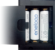
Power supply
Power is provided from an external AC adapter, and operation of the device (except Ethernet interface) is backed up by replaceable batteries. The device can be used permanently installed or as portable device with the option to charge batteries directly using the AC adapter or using standard alkaline batteries size AA. Battery life is several months.
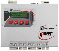
Variable 16 input-channel datalogger
Monitoring system
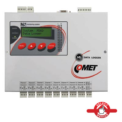
Main features
- software configurable or modular inputs for
- - temperature sensors Pt and Ni
- - thermocouples and thermistors
- - voltage and current
- - two-state events
- - frequency and pulses
- - resistance
- - sensors with RS485 output
- memory for 500 000 records with automatic downloading to PC
- alarm indication via integrated siren,
- e-mail, SMS and two-state output to control other devices
- software for data analysis on PC
- communication interface USB, RS232, relays, RS485 (Modbus RTU),
- ETHERNET (Modbus TCP, SOAP, etc.)
Monitoring systems MS - models and variations
MS6D and its variations
Each Monitoring System contains 16 software configurable inputs.
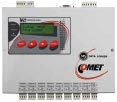
MS55D
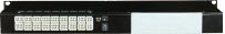
The user can select the hardware modules to be fitted into the monitoring system MS.
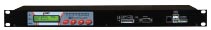
MS6-Rack - For mounting to 19“ rack
MS6R - MS6R - For deskopt use

| main differences | MS6D | MS55D |
|---|---|---|
| inputs | 16 software programmable inputs | 1 - 16 hardware input modules |
| maximum measured DC current | 20 mA dc | 5 A dc |
| maximum measured DC voltage | 10 V dc | 75 V dc |
| most sensitive measuring range of dc voltage | 18 mV dc | 100 mV dc |
| maximum measured AC current | - | 5 A dc |
| maximum measured AC voltage | - | 50 V ac |
| input for measurement of frequency | - | 0 to 5 kHz |
| input for counting of pulses | - | Yes |
Recording
Recorded values are stored to a non volatile electronic memory.
Various options for data recording
In addition to continuous recording mode with a constant interval can also enjoy a variety of other options. You can record data with its own interval only when certain conditions are valid, which may depend on measured values , time or direct user intervention. For example, you can control recording via an external contact or it is possible to set faster sampling mode during alarm conditions.
In case of power failure
In the event of a power failure, the backed up datalogger will continue to measure. Recorded data contains date and time of power failure. If the data logger is connected to GSM modem, the operator is immediately aware of difficulties.
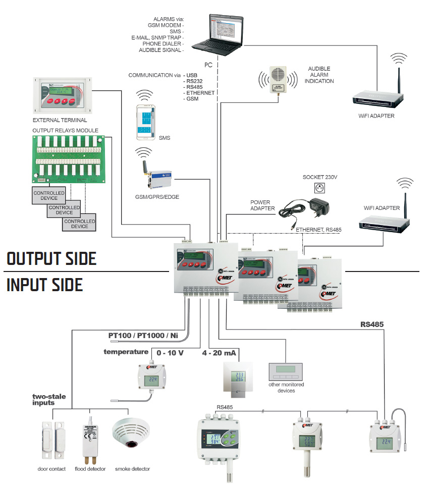
Alarms and Communication interfaces
- Alerts via:
- » External siren or lights re
- » Email messages
- » SMS texts via connected
- GPRS modem or router
- » Telephone dialer
Relay on
Monitoring system MS activates selected relays (integrated relay ALARM OUT or external relays module) depending on alarm states.You can combine up to 16 switching external relay depending on arisen conditions. One of these conditions can be controlled via SMS messages.
Communication through GSM modem, GPRS / EDGE router
Modems can be used to set up a monitoring system MS, reading the recorded data, reading the current values and to communicate via SMS messages. The offered modems have been thoroughly tested to ensure maximum reliability.
Alerts via SMS texts
All data loggers are equipped with RS232 interface. GSM modem (GPRS router)
can be connected to that port for transmitting alarm SMS texts. Up to four phone numbers can be set. Using text messages
can also read the current values .
Email messages
Because of Ethernet interface you
can expand communication possibilities of measuring system MS. Then alarm emails are sent directly to your email inbox.
You can also read the current data via web browser.
Common connectivity options
Parameters of conf gurable inputs MS6D
|
Measured values |
Range |
Accuracy |
Note |
|---|---|---|---|
|
DC |
4 to 20 mA |
±0.1% FS (±0.02 mA) |
it is possible to connect pasive sensors (powered by monitoring system) or active sensor with its own power supply. Input resistance about 110 Ohms. |
|
DC |
-10 V to+10 V |
±0.1% FS (±10 mV) |
Input resistance about 10 MOhms |
|
-1 V to +1 V |
±0.1% FS (±1 mV) |
||
|
-100 mV to +100 mV |
±0.1% FS (±100 uV) |
||
|
-18 mV to +18 mV |
±0,1% FS (±18 uV) |
||
|
two-wire resistance Measurement |
0 to 300 Ohms |
±0.1% FS (±0.3 Ohms) |
measuring current approximately 0.8 mA @ 50 ms pulse |
|
0 to 3000 Ohms |
±0.1% FS (±3 Ohms) |
measuring voltage approximately 0.5 mA @ 50 ms pulse |
|
|
0 to 10000 Ohms |
±0.1% FS (±10 Ohms) |
measuring current approximately 0.1 mA @ 50 ms pulse |
|
|
Ni1000 |
-50 °C to +250 °C |
±0.2 °C (-50 °C to 100 °C) |
Ni1000/6180 ppm, two-wire connection |
|
±0.2 % MV (100 °C to 250 °C) |
measuring current approximately 0.5 mA @ 50 ms pulse |
||
|
Pt100 |
-200 °C to +600 °C |
±0.2 °C (-200 °C to+100 °C) |
Pt100/3850 ppm, two-wire connection |
|
±0.2 % MV (+100 °C to +600 °C) |
measuring current approximately 0.8 mA @ 50 ms pulse |
||
|
Pt1000 |
-200 °C to +600 °C |
±0.2 °C (-200 °C to+100 °C) |
Pt1000/3850 ppm, two-wire connection |
|
±0.2 % MV (+100 °C to +600 °C) |
measuring current about 0.5 mA @ 50 ms pulse |
||
|
K (NiCr-Ni) |
-200 °C to 1300 °C |
±(0.3 % MV +1.5 °C) MS6D only |
linearized, with cold junction compensation, datalogger must be placed in recommendend working position |
|
T (Cu-CuNi) |
-200 °C to 400 °C |
||
|
J (Fe-Co) |
-200 °C to 750 °C |
||
|
S (Pt10 % Rh-Pt) |
0 to 1700 °C |
||
|
N (NiCrSi-NiSiMg) |
-200 °C to 1300 °C |
||
|
B (Pt30 % Rh-Pt) |
100 °C to 1800 °C |
linearized, without cold junction compensation |
|
|
NTC with selectable Formula |
up to maximum thermistor resistance 11000 Ohms |
according to the used resistance range (see measurement of resistance) |
the same characteristics for all connected thermistors |
|
default settings: R25=2252 Ohms, R80 = 282.7 Ohms |
|||
|
potential-less contact |
binary signal |
input voltage for state „L“ (IN-COM) < 0.8 V |
|
|
input voltage for state „H“ (IN-COM) > 2 V |
|||
|
open collector |
resistance of closed contact for state „L“ (IN-COM) < 1 kOhms |
||
|
voltage levels |
resistance of open contact for state „H“ (IN-COM) > 10 kOhms“ |
||
|
minimum duration for sensing of change: 200 ms |
|||
|
input for serial signal RS485 |
on request |
input serves for reading from devices supporting protocol Mod- Bus RTU or Advantech |
|
|
connected to terminals next to terminals for channel 15 and 16 |
|||
|
input can work with 16 devices |
|||
|
galvanically isolated |
|||
Parameters of inputs MS55D
|
Measured values |
Module types |
Range |
Accuracy |
Notes |
|---|---|---|---|---|
|
DC |
A0 |
4 to 20 mA |
±0.1 % FS |
with source approximately 21V for two-wire transducers with current loop (e.g. temperature and humidity transducers Comet). |
|
A1* |
4 to 20 mA |
only galvanic not isolated |
||
|
B0* |
0 to 20mA |
for passive sensing of current, Rin = 14 Ohms |
||
|
B1* |
0 to 1 A |
input resistance Rin = 0.04 Ohms |
||
|
B2* |
0 to 5 A |
|||
|
AC |
C0 |
0 to 20 mA |
±1 % FS |
galvanic isolated, sinusoidal signal at a frequency of 50 Hz input C1 0 to 1 A resistance Rin by type 0.04 Ohm to 14 Ohms |
|
C1 |
0 to 1 A |
±1 % FS |
||
|
C2 |
0 to 5 A |
|||
|
DC |
D0* |
0 to 100 mV |
±0.1 % FS |
input resistance Rin by a 900 kOhms to 10 Mohms |
|
D1* |
0 to 1 V |
|||
|
D2* |
0 to 10 V |
|||
|
D4* |
0 to 75 V |
|||
|
D5* |
-10 V to +10 V |
±0.1 % FS (± 20 mV) |
||
|
AC |
E0 |
0 to 100 mV |
±1 % FS |
only galvanic isolated, sinusoidal signal at a frequency of 50 Hz input resistance Rin by type 700 kOhms to 10 Mohms |
|
E1 |
0 to 1 V |
|||
|
E2 |
0 to 10 V |
|||
|
E4 |
0 to 50 V |
|||
|
resistance |
F* |
must be specified |
±0.1 % FS |
two-wire connection |
|
Ni1000 |
J* |
-50 °C to +250 °C |
±0.2 °C (-50 °C to 100 °C) |
Ni1000/6180 ppm, two-wire connection |
|
±0.2% MV (100 °C to 250 °C) |
measuring current of approximately 0.25 mA continuously |
|||
|
Pt100 |
K* |
-140 °C to +600 °C |
±0.2 °C (-140 °C to +100 °C) |
Pt100/3850 ppm, two-wire connection |
|
±0.2 % MV (+100 °C to +600 °C) |
measuring current of approximately 2 mA continuously |
|||
|
Pt1000 |
K1* |
-140 °C to +600 °C |
±0.2 °C (-140 °C to +100 °C) |
Pt1000/3850 ppm, two-wire connection |
|
±0.2 % MV (+100 to +600 °C) |
measuring current of approximately 0.2 mA continuously |
|||
|
Pt1000 |
k3 |
-10 °C to +50 °C |
C ±0.06 °C |
Pt1000/3850 ppm, two-wire connection |
|
measuring current of approximately 0.2 mA continuously |
||||
|
K (NiCr-Ni) |
N* |
-70 °C to +1300 °C |
±0.3 % MV + 1.5 °C |
linearized, cold junction compensation, datalogger must be placed in recommendend working position |
|
T (Cu-CuNi) |
T* |
-200 °C to +400 °C |
||
|
J (Fe-Co) |
O* |
-200 °C to 750 °C |
||
|
S (Pt10 %Rh-Pt) |
P* |
0 °C to 1700 °C |
±0.3 % MV +1.5 °C (200 °C to 1700 °C) |
|
|
B (Pt30 %Rh-Pt) |
Q* |
100 °C to 1800 °C |
±0.3 % MV+1.0 °C (300 °C to 1800 °C) |
linearized, without cold junction compensation |
|
potential-less Contact |
S* |
binary signal |
maximum resistance of closed contact is 1000 Ohms |
|
|
minimum duration for recording is 200 ms |
||||
|
voltage, galvanically Isolated |
S1 |
binary signal |
voltage for „H“ state is 3 V to 30 Vdc @ 9 mA max |
|
|
minimum duration for recording: 200 ms |
||||
|
galvanically isolated |
||||
|
potential-less contact, galvanically Isolated |
CTU |
31 bits, 5kHz max. |
voltage change of the counter state is 3 V to 24 Vdc |
|
|
backup power, filter bouncing |
||||
|
galvanically isolated |
||||
|
potential-less contact, open connector |
CTK |
31 bits, 5kHz max. |
maximum resistance of closed contact is 10 kOhms |
|
|
minimum open contact resistance is 250 kOhms |
||||
|
backup power, filter bouncing |
||||
|
input voltage signal measurement, galvanically Isolated |
FU |
0 to 5 kHz |
±(0.2 % MV + 1 Hz)±(0.2 % MV + 1 Hz) |
input voltage for „H“: 3 V to 24 Vdc @ 7 mA |
|
minimum duration of input pulse: 30 us |
||||
|
resolution 1Hz |
galvanically isolated |
|||
|
measurement frequency switching contact, galvanically |
FK |
0 to 5 kHz |
±(0.2 % MV + 1 Hz)±(0.2 % MV + 1 Hz) |
maximum resistance of closed contact is 10 kOhms |
|
minimum open contact resistance is 250 kOhms |
||||
|
resolution 1Hz |
minimum duration of input pulse: 30 us |
|||
|
input for serial signal RS485 |
RP |
digital transmission |
input supports Modbus RTU or Advantech |
|
|
connected devices must have the same communication parameters |
||||
|
input can work with up to 16 devices |
||||
|
galvanic isolated, MS can be equiped wit multiple RP modules |